#include <avr/io.h>#include <stdint.h>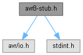
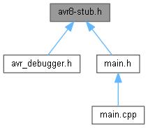
Ir al código fuente de este archivo.
defines | |
| #define | AVR8_BREAKPOINT_MODE (1) |
| #define | AVR8_USE_TIMER0_INSTEAD_OF_WDT (0) |
| #define | AVR8_USE_TIMER0_INSTEAD_OF_WDT (0) |
| #define | AVR8_SWINT_SOURCE (0) |
| #define | AVR8_LOAD_SUPPORT (0) |
| #define | AVR8_UART_NUMBER 0 |
| #define | AVR8_MAX_BREAKS (8) |
Funciones | |
| void | debug_init (void) |
| void | breakpoint (void) |
| void | debug_message (const char *msg) |
Documentación de «define»
◆ AVR8_BREAKPOINT_MODE
| #define AVR8_BREAKPOINT_MODE (1) |
AVR8_BREAKPOINT_MODE Select the mode for handling breakpoints and step command. Options: 0 - FLASH breakpoints with avr-stub bootloader 1 - RAM only - RAM breakpoints and stepping 2 - FLASH breakpoints with Optiboot bootloader (using do_spm() function)
More info: RAM breakpoints - use external interrupt to stop the program after each instruction and compare PC with breakpoints. If any BP address is reached, the program is halted. Program runs slow with BP enabled. (+) No wear of flash memory (-) Debugged program runs slowly - interrupt occurs after every instruction and in the ISR there are perhaps 100 cycles needed to save and restore context. How much the debugged program is affected depends also on the design of the program, for example, blinking LED with delays based of poling timer value may be affected little, while delays using busy loop will be much much longer than expected.
Flash breakpoints - writes special instruction at the position where program should stop. (-) Flash memory is overwritten often during debug session. It should survive 10 000 erase-write cycles. (+) Debugged program runs at normal (full) speed between breakpoints.
Note: The step command (going to next line) is implemented by comparing the PC register with desired address even in FLASH breakpoints mode. In principle it would be possible to implement it by writing to flash but it would wear the flash memory very fast. There are about 10 overwrites for a single step in the debugger in such case.
Definición en la línea 119 del archivo avr8-stub.h.
◆ AVR8_LOAD_SUPPORT
| #define AVR8_LOAD_SUPPORT (0) |
AVR8_LOAD_SUPPORT Enable or disable support for loading the program from the debugger. If enabled you can just click the Debug button in IDE to upload new program and debug it. IMPORTANT: requires support in bootloader so the bootloader in Arduino must be replaced with the bootloader provided in this package. It doesn't work with the Optiboot bootloader
Options: 0 - load from GDB disabled. Load the program using avrdude as usual. 1 - load from GDB enabled.
Definición en la línea 213 del archivo avr8-stub.h.
◆ AVR8_MAX_BREAKS
| #define AVR8_MAX_BREAKS (8) |
Maximum number of breakpoints supported. Note that gdb will set temporary breakpoint, for example, for step into function or the Run to line command, so the actual number of breakpoints user can set will be lower. For flash breakpoints it is better to use lower number - each breakpoint means writing to flash, user will often forget about old breakpoints and these will be rewritten to flash with no need...So it is better to limit the number and make the user delete breakpoints when not needed. It is quite possible to debug a program with single breakpoint.
Definición en la línea 258 del archivo avr8-stub.h.
◆ AVR8_SWINT_SOURCE
| #define AVR8_SWINT_SOURCE (0) |
AVR8_SWINT_SOURCE Source for software interrupt. Valid values are listed below. The pin selected here will be used for generating SW interrupt by the debugger and cannot be used for anything else - it becomes reserved for the debugger.
Supported values for Atmega328 (UNO): 0 - use INT0 (pin PD2, Arduino pin 2) 1 - use INT1 (pin PD3, Arduino pin 3)
Supported values for ATmega1284(P): 0 - use INT0 (pin PD2) 1 - use INT1 (pin PD3) 2 - use INT3 (pin PB2)
Supported values for Atmega2560 and Atmega1280: TIP: Use value 6 or 7; the pins for these INTs are not connected on Arduino mega board, so you will not waste any pin. 0 - INT0 (pin PD0, Arduino pin 21) 1 - INT1 (pin PD1, Arduino pin 20) 2 - INT2 (pin PD2, Arduino pin 19) 3 - INT3 (pin PD3, Arduino pin 18) 4 - INT4 (pin PE4, Arduino pin 2) 5 - INT5 (pin PE5, Arduino pin 3) 6 - INT6 (pin PE6, not used on Arduino) 7 - INT7 (pin PE7, not used on Arduino) Note to implementors INT0-3 uses EICRA reg. and port D INT4 - 7 uses EICRB reg. and port E Pins PE6 and PE7 are not connected on Arduino Mega boards.
NOTE: Special value -1 can be defined to use output compare interrupt of timer0 instead of external interrupt. IMPORTANT:
- The debugger may not work properly if any interrupt with higher priority that the timer0 compare interrupt (TIMER0 COMPA) is enabled in the debugged program.
- analogWrite for the pin connected to COMPA channel of timer0 (pin 6 on Arduino Uno) may be affected by this option. This option is only available if you use FLASH breakpoints (see AVR8_BREAKPOINT_MODE).
Note: Pin Change Interrupt (PCINT) could be used also. It could be one of the Arduino analog pins (PC0 - PC5) which are less likely to be used by the user program. Note that if PCINT is used, then INT0 and INT1 used by the user program could cause troubles, because they have higher priority than PCINT and could prevent the debugger from catching the program properly...
Definición en la línea 195 del archivo avr8-stub.h.
◆ AVR8_UART_NUMBER
| #define AVR8_UART_NUMBER 0 |
UART module used by the debugger. This select the serial communication peripheral used for communicating with the GDB.
This option only makes sense for Arduino Mega because the Atmega2560 and 1280 have 4 hardware UARTs. By using other UART than the UART0 you can use this debugger together with the Arduino Serial functions. For Arduino boards based on ATmega328 (like Uno, Nano,...) the only valid option is 0 (to use UART0) because there are no other hardware UARTs.
Supported values for Atmega328 (UNO): 0 - use USART0 (Arduino Serial cannot be used with the debugger)
Supported values for ATmega1284(P): 0 - use USART0 1 - use USART1
Supported values for Atmega2560 and Atmega1280: 0 - use USART0 (Arduino Serial cannot be used with the debugger) 1 - use USART1 (Rx=PD2=D19, Tx=PD3=D18) 2 - use USART2 (Rx=PH0=D17, Tx=PH1=D16) 3 - use USART3 (Rx=PJ0=D15, Tx=PJ1=D14)
Note: the number in AVR8_UART_NUMBER is used to generate register names in macros; don't put it into parentheses.
Definición en la línea 243 del archivo avr8-stub.h.
◆ AVR8_USE_TIMER0_INSTEAD_OF_WDT [1/2]
| #define AVR8_USE_TIMER0_INSTEAD_OF_WDT (0) |
AVR8_USE_TIMER0_INSTEAD_OF_WDT Select one of the following options for the interrupt to detect that the program stopped on a breakpoint: 0 - do not use TIMER0 interrupts but the watchdog timer interrupt 1 - use the output compare A interrupt of timer 0 (the timer for millis and delays)
Using the watchdog timer is the default, but it means that we cannot use the watchdog timer in the user program.
The other option is to use the output compare interrupt A of timer0 (TIMER0 COMPA). To use this option your program must use the Arduino core and timer0 must be configured by this core. Since the timer is used by Arduino for counting milliseconds, this is usually the case. With this option enabled, the user program can use watchdog timer.
Definición en la línea 139 del archivo avr8-stub.h.
◆ AVR8_USE_TIMER0_INSTEAD_OF_WDT [2/2]
| #define AVR8_USE_TIMER0_INSTEAD_OF_WDT (0) |
AVR8_USE_TIMER0_INSTEAD_OF_WDT Select one of the following options for the interrupt to detect that the program stopped on a breakpoint: 0 - do not use TIMER0 interrupts but the watchdog timer interrupt 1 - use the output compare A interrupt of timer 0 (the timer for millis and delays)
Using the watchdog timer is the default, but it means that we cannot use the watchdog timer in the user program.
The other option is to use the output compare interrupt A of timer0 (TIMER0 COMPA). To use this option your program must use the Arduino core and timer0 must be configured by this core. Since the timer is used by Arduino for counting milliseconds, this is usually the case. With this option enabled, the user program can use watchdog timer.
Definición en la línea 139 del archivo avr8-stub.h.
Documentación de funciones
◆ breakpoint()
| void breakpoint | ( | void | ) |
Insert breakpoint at the position where this function is called. To set-up breakpoints before compilation.
◆ debug_init()
| void debug_init | ( | void | ) |
Define this to enable some global variables to make it easier to debug this stub. This is for advanced users who need to debug the debugger (gbd stub) itself. Initialize the debugger driver ? Is this our version of set_debug_traps ? (see above) But the interrupts are re-directed in compile time, so we do not need such function.

◆ debug_message()
| void debug_message | ( | const char * | msg | ) |
Send text message to gdb console. The function appends "\n" to the msg. Note that GDB will queue the messages until "\n" (0x0a) is received; then it displays the messages in console.